Заява аб прыватнасці: Ваша прыватнасць для нас вельмі важная. Наша кампанія абяцае не раскрываць вашу асабістую інфармацыю любой экспазіцыі з вашымі відавочнымі дазволамі.
мадэль №: NSO4GU3AB
транспарт: Ocean,Air,Express,Land
тып аплаты: L/C,T/T,D/A
Інкатэрм: FOB,EXW,CIF
4 Гб 1600 МГц 240-кантактны DDR3 UDIMM
Гісторыя перагляду
|
Revision No. |
History |
Draft Date |
Remark |
|
1.0 |
Initial Release |
Apr. 2022 |
|
![]()
Інфармацыйная табліца замовы
|
Model |
Density |
Speed |
Organization |
Component Composition |
|
NS04GU3AB |
4GB |
1600MHz |
512Mx64bit |
DDR3 256Mx8 *16 |
Апісанне
Hengstar Unmbuffered DDR3 SDRAM DIMMS (Unmbuffered Double Data Synchronous DRAM DUAL In-LINE MEMULE)-гэта нізкая магутнасць, хуткасныя модулі памяці, якія выкарыстоўваюць прылады DDR3 SDRAM. NS04GU3AB-гэта 512M X 64-бітны два рангу 4GB DDR3-1600 CL11 1.5V SDRAM UNBUFFERED DIMM, заснаваны на шаснаццаці 256 м х 8-бітных кампанентаў FBGA. SPD запраграмаваны да стандартнай затрымкі JEDEC DDR3-1600 тэрмінаў 11-11-11 пры 1,5 У. Кожны 240-кантактны DIMM выкарыстоўвае залатыя кантактныя пальцы. SDRAM UNBUFFERED DIMM прызначаны для выкарыстання ў якасці асноўнай памяці пры ўсталёўцы ў такіх сістэмах, як ПК і працоўныя станцыі.
Асаблівасці
Power харчаванне: VDD = 1.5V (1,425V да 1,575V)
VDDQ = 1,5V (1,425V да 1,575V)
FCK FCK для 1600 Мб/сек/штыфт
8 Незалежны ўнутраны банк
Праграмаваны затрымка CAS: 11, 10, 9, 8, 7, 6
Праграмаваную затрымку дабаўкі: 0, Cl - 2 або Cl - 1 гадзіннік
8-бітны папярэдні зварот
Даўжыня Burst: 8 (Interleave без якіх -небудзь абмежаванняў, паслядоўны з стартавым адрасам "толькі 000"), 4 з TCCD = 4, што не дазваляе бесперашкодна чытаць альбо пісаць [альбо на хаду, выкарыстоўваючы A12, альбо MRS]
Bi-кіруе дыферэнцыяльнымі дадзенымі строба
Інтэрнэт -каліброўка (самаадчуванне); Унутраная каліброўка самастойна праз штыфт ZQ (RZQ: 240 Ом ± 1%)
on die скасаванне пры дапамозе штыфта ODT
Оверт -перыяд абнаўлення 7,8U на ніжэйшы за TSACE 85 ° C, 3,9US пры 85 ° C <TSACE <95 ° C
asynchronous Reset
Адрэгулюецца сіла прывада дадзеных-вываду
Fly-by тапалогія
PCB: Вышыня 1,18 ”(30 мм)
ROHS, якія адпавядаюць і без галагена
Ключавыя параметры часу
|
MT/s |
tRCD(ns) |
tRP(ns) |
tRC(ns) |
CL-tRCD-tRP |
|
DDR3-1600 |
13.125 |
13.125 |
48.125 |
2011/11/11 |
Адрас табліцы
|
Configuration |
Refresh count |
Row address |
Device bank address |
Device configuration |
Column Address |
Module rank address |
|
4GB |
8K |
32K A[14:0] |
8 BA[2:0] |
2Gb (256 Meg x 8) |
1K A[9:0] |
2 S#[1:0] |
Апісанні штыфта
|
Symbol |
Type |
Description |
|
Ax |
Input |
Address inputs: Provide the row address for ACTIVE commands, and the column |
|
BAx |
Input |
Bank address inputs: Define the device bank to which an ACTIVE, READ, WRITE, or |
|
CKx, |
Input |
Clock: Differential clock inputs. All control, command, and address input signals are |
|
CKEx |
Input |
Clock enable: Enables (registered HIGH) and disables (registered LOW) internal circuitry |
|
DMx |
Input |
Data mask (x8 devices only): DM is an input mask signal for write data. Input data is |
|
ODTx |
Input |
On-die termination: Enables (registered HIGH) and disables (registered LOW) |
|
Par_In |
Input |
Parity input: Parity bit for Ax, RAS#, CAS#, and WE#. |
|
RAS#, |
Input |
Command inputs: RAS#, CAS#, and WE# (along with S#) define the command being |
|
RESET# |
Input |
Reset: RESET# is an active LOW asychronous input that is connected to each DRAM and |
|
Sx# |
Input |
Chip select: Enables (registered LOW) and disables (registered HIGH) the command |
|
SAx |
Input |
Serial address inputs: Used to configure the temperature sensor/SPD EEPROM address |
|
SCL |
Input |
Serial |
|
CBx |
I/O |
Check bits: Used for system error detection and correction. |
|
DQx |
I/O |
Data input/output: Bidirectional data bus. |
|
DQSx, |
I/O |
Data strobe: Differential data strobes. Output with read data; edge-aligned with read data; |
|
SDA |
I/O |
Serial |
|
TDQSx, |
Output |
Redundant data strobe (x8 devices only): TDQS is enabled/disabled via the LOAD |
|
Err_Out# |
Output (open |
Parity error output: Parity error found on the command and address bus. |
|
EVENT# |
Output (open |
Temperature event: The EVENT# pin is asserted by the temperature sensor when critical |
|
VDD |
Supply |
Power supply: 1.35V (1.283–1.45V) backward-compatible to 1.5V (1.425–1.575V). The |
|
VDDSPD |
Supply |
Temperature sensor/SPD EEPROM power supply: 3.0–3.6V. |
|
VREFCA |
Supply |
Reference voltage: Control, command, and address VDD/2. |
|
VREFDQ |
Supply |
Reference voltage: DQ, DM VDD/2. |
|
VSS |
Supply |
Ground. |
|
VTT |
Supply |
Termination voltage: Used for control, command, and address VDD/2. |
|
NC |
– |
No connect: These pins are not connected on the module. |
|
NF |
– |
No function: These pins are connected within the module, but provide no functionality. |
Заўвагі : У табліцы апісання PIN ніжэй прыведзены вычарпальны спіс усіх магчымых штыфтоў для ўсіх модуляў DDR3. Усе пералічаныя штыфты могуць быць не падтрымліваецца на гэтым модулі. Гл. Заданні PIN -кода для інфармацыі, характэрнай для гэтага модуля.
Функцыянальная блок -схема
4GB, модуль 512mx64 (2Rank x8)


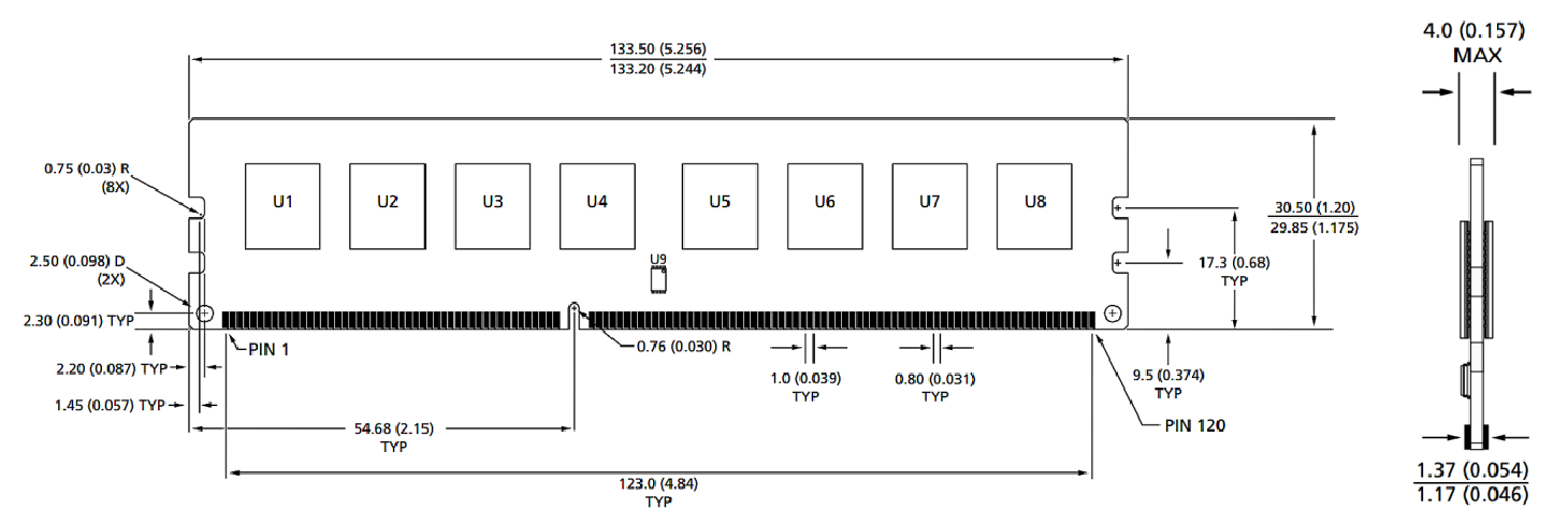
Памеры модуля
Выгляд спераду

Выгляд спераду

Заўвагі:
1. Усе памеры ў міліметрах (цалі); Макс/мін альбо тыповы (тып), дзе адзначана.
2. Воларасць пры ўсіх памерах ± 0,15 мм, калі не паказана іншае.
3. Памерная схема прызначана толькі для даведкі.
катэгорыі прадуктаў : Індустрыяльны смарт -модульны аксэсуары


Заява аб прыватнасці: Ваша прыватнасць для нас вельмі важная. Наша кампанія абяцае не раскрываць вашу асабістую інфармацыю любой экспазіцыі з вашымі відавочнымі дазволамі.

Запоўніце дадатковую інфармацыю, каб хутчэй звязацца з вамі
Заява аб прыватнасці: Ваша прыватнасць для нас вельмі важная. Наша кампанія абяцае не раскрываць вашу асабістую інфармацыю любой экспазіцыі з вашымі відавочнымі дазволамі.